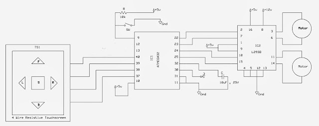
The objective of this project/tutorial is to build a 4 wire Resistive Touch Screen controlled Robot with ATmega32 microcontroller. Here, the 4 wire resistive touch screen sensor act as the input device, ATmega32 microcontroller act as the processing unit, DC Motor Driver act as the driver for the motors connected to the Robot, The ATmega32 microcontroller reads the analog output values(x and y-axis values of the touch point) of the 4 wire resistive touch screen sensor and converts that analog values to digital values with its analog to digital converter.
Then, the digital values are processed by the ATmega32 microcontroller and according to the point of touch in the 4 wire resistive touch screen, the ATmega32 microcontroller drives the Robot in forward, reverse, left, right direction and stops it. The direction of the Robot changes if the connection of motors to the DC Motor Driver are changed.
Port A of ATMEGA32 is used as input port while Port C is used as output port to control the motor driver IC2 L293D. Software used to debug the code is AVR Studio.
 |
| Block Diagram |
Port A of ATMEGA32 is used as input port while Port C is used as output port to control the motor driver IC2 L293D. Software used to debug the code is AVR Studio.
 |
| Circuit Diagram |
To download the code for this project click on below button :
