Flashing lights have varied applications. For example, travellers can use these as warning beacons on highways to catch the attention of the public in case of an emergency. Described here is the circuit of a battery-operated, LED-based portable signal wand.
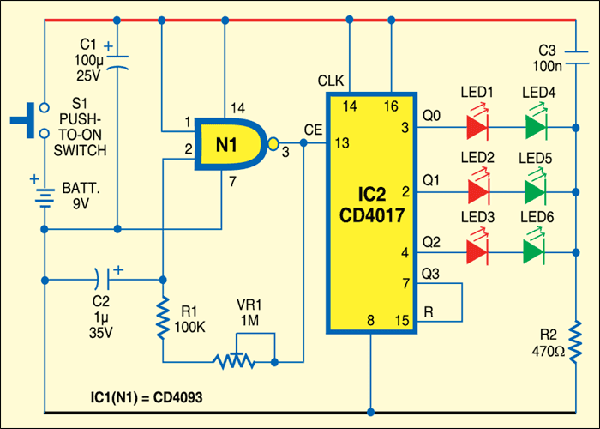
The signal wand is in fact a three channel, sequential dual-colour LED flasher built around two popular and inexpensive chips—CD4093 and CD4017. CD4093 (IC1) consists of four in built Schmitt-trigger circuits. Each circuit functions as a two-input NAND gate with Schmitt-trigger action on both the inputs. Here one gate (N1) of IC1 is wired as a gated astable multivibrator with its control pin 1 permanently connected to the positive supply as shown in Fig. 1. The frequency of the astable multivibrator can be varied with the help of a 1-mega-ohm preset (VR1). CD4017 (IC2) is a five-stage divide-by-ten Johnson counter with ten decoded outputs and a carry bit.
Counter IC2 is cleared to zero count by a logic high on its reset pin. IC2 advances by one count on the positive edge of the clock signal when the clock-enable signal is in the logic-low state. Ten decoded outputs of IC2 (Q0 through Q9) are normally low and reach high state only at their respective time-slot. Each decoded output remains high for a full clock cycle.
The clock output from gated astable N1 is fed to clock-enable pin (pin 13) of IC2. The clockinput (pin 14) of IC2 is permanently high. Three outputs of IC2 (Q0 through Q2) are connected to three independent LED strings. Each LED string consists of a red and a green LED in series with a common current limiting resistor R2. The fourth output (Q3) of IC2 is returned to its reset terminal (pin 15).
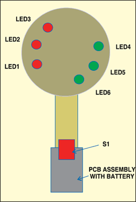
Assemble the circuit on a general-purpose PCB. After assembling and testing, enclose the circuit along with a 9V battery in a transparent tube as shown in Fig.2. Use of low-current, high brightness 5-millimetre LEDs is recommended.
SCHEMATIC :

